
Chip Load and Feed Rate: A Verification-First Method
How feed rate, spindle speed, flute count, and engagement relate, with a conservative validation loop for desktop CNC routing.
Table of Contents▼
The relationship
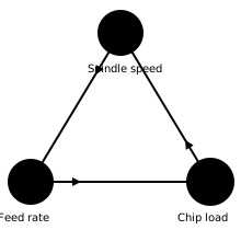
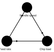
For a rotating cutter, nominal chip load per tooth can be estimated as:
$$ f_z = \frac{V_f}{n \cdot z} $$
where:
- (f_z) is nominal chip load per tooth in mm/tooth;
- (V_f) is programmed feed rate in mm/min;
- (n) is spindle speed in RPM;
- (z) is the number of effective cutting flutes.
The rearranged feed-rate relationship is:
$$ V_f = f_z \cdot n \cdot z $$
This is a relationship between programmed variables. It is not a universal material chart and it does not include every factor that affects actual chip thickness.
A small example, not a recommendation
Suppose a two-flute tool is programmed at 18,000 RPM and 1,800 mm/min:
chip load = 1,800 / (18,000 × 2)
chip load = 0.05 mm/tooth
The arithmetic is useful for checking a program. It does not tell you whether the tool is sharp, whether the machine is rigid enough, or whether the material and workholding can tolerate the cut. Changing the flute count without changing the feed changes the result.
Nominal chip load is not the whole cut
The formula assumes a simple relationship between the feed and the cutting edges. Actual chip thickness changes with radial engagement, axial depth, cutter geometry, runout, tool sharpness, material, climb or conventional direction, and the rigidity of the machine.
Low radial engagement can reduce the actual maximum chip thickness. Do not apply a fixed “increase feed by 10–30%” rule without a source for the exact tool and operation. When the engagement changes, use the tool maker's chip-thinning guidance if available, then validate the result on scrap.
Material scope matters
Wood, plywood, MDF, plastics, aluminum, and fiber-reinforced composites do not share one safe chip-load window. Tool geometry, coating, spindle capability, machine rigidity, dust or chip extraction, and workholding all matter.
For Laetoly's desktop-CNC examples, begin with the documented wood or plywood baseline and keep the test cut shallow. This page does not authorize aluminum or composite cutting on an unverified machine. For plastics, avoid treating “more feed” as the only correction: chip evacuation and heat removal are part of the setup. For metals and composites, use material- and tool-specific manufacturer data and an appropriate machine assessment.
A verification loop
- Record the tool diameter, flute count, stickout, material, machine, and workholding.
- Select a starting chip-load range from the tool maker or an approved internal note.
- Calculate the programmed feed and confirm it is inside the machine and spindle limits.
- Reduce depth and engagement for the first scrap test.
- Run a spindle-off clearance check, then cut only a small test feature.
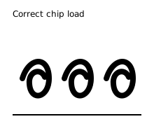
- Observe chips, sound, edge quality, movement, heat, and missed steps.
- Change one variable at a time and record the result.
What to do when the cut looks wrong
- Fine dust or rubbing: stop and reassess tool sharpness, feed, RPM, engagement, and extraction. Do not blindly lower the feed.
- Burning or melted material: stop the cut and investigate heat, chip evacuation, tool geometry, and material compatibility.
- Chatter or deflection: reduce engagement, shorten stickout, improve workholding, or use a more rigid setup before chasing a number.
- Broken tool or lost steps: treat the setup as unverified. Inspect the workpiece, clamp, tool, and controller state before any retry.
Chip load makes parameter changes explainable. It does not remove the need for machine limits, conservative testing, and an explicit stop condition.