
Choosing Router Bits by Flute Geometry
A practical guide to up-cut, down-cut, compression, flute count, and cutter rigidity for desktop CNC routing.
Table of Contents▼
Start with the edge and chip problem
Router bits are easier to choose when you begin with the result you need rather than the name on the package. Ask two questions:
- Which surface needs the cleanest edge?
- Where must the chips go so they do not pack, recut, or overheat the cut?
| Geometry | Typical effect | Trade-off to check |
|---|---|---|
| Up-cut spiral | Lifts chips out of the cut and usually improves chip evacuation | The top edge may show more fuzz or tear-out; chips need extraction |
| Down-cut spiral | Pushes chips toward the workpiece and can improve the visible top edge | Chips can collect in a pocket or blind slot and may be recut |
| Compression spiral | Combines up-cut and down-cut sections for two-sided sheet work | The result depends on cut depth; a shallow pass may not engage the compression section |
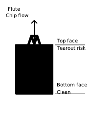
Do not interpret “up-cut” or “down-cut” as a quality ranking. They are different chip-flow choices. In a pocket, a down-cut tool can make a clean top edge while leaving chips in the pocket. In a through-cut, an up-cut tool may evacuate chips better while increasing top-edge fuzz. The correct choice depends on which trade-off your operation can accept.
When compression geometry is appropriate
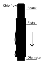
A compression bit is useful when both the top and bottom faces of a laminated sheet need edge control. It only works as intended when the toolpath reaches the part of the cutter where the opposing flute directions overlap the material. Follow the tool maker's recommended minimum engagement and do not assume that one shallow pass will produce a compression cut.
For ordinary plywood or MDF, start with the simplest geometry that solves the edge problem. A compression cutter is not automatically better, and a more complex cutter may make chip evacuation and parameter selection harder.
Use flute count as a constraint, not a score
Flute count changes the available chip space and the relationship between feed rate, RPM, and chip load. A single-flute tool may provide more room for chips when the machine and material support it. A two-flute tool is a common woodworking starting point. Higher flute counts can suit particular finishing or material-removal strategies, but they also change the required feed and chip-clearance behavior.
Never copy a feed value from a different flute count. Use the formula and tool maker's chart for the actual tool, then validate on scrap.
Prefer the shortest cutter that reaches the job
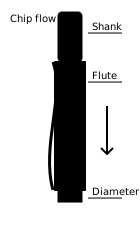
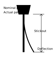
Longer cutting length increases reach but usually reduces rigidity. A “three times diameter” relationship can be used as a warning boundary in early tool selection, not as a universal safety limit. Tool material, shank diameter, stickout, machine rigidity, radial engagement, and feed all affect deflection.
Choose enough cutting length to clear the workpiece and no more. Keep the stickout as short as the collet and workholding allow, and verify that the collet grips the shank rather than the flutes.
Separate roughing from finishing
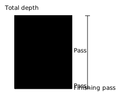
The cutter that removes most of the material does not have to establish the final dimension. A roughing pass can leave a small, deliberate allowance. A finishing pass can then remove that allowance with a lower engagement and a more predictable edge.
This strategy is useful when dimensional accuracy or visible edge quality matters, but it does not remove the need for workholding, toolpath simulation, and a test cut.
A repeatable selection checklist
- Identify the material, thickness, visible faces, and whether the operation is a pocket, profile, or through-cut.
- Select the chip direction that matches the edge and evacuation requirement.
- Confirm the cutter diameter, flute count, cutting length, shank, and manufacturer limits.
- Use the shortest practical cutting length and the minimum stickout that still clears the work.
- Set a conservative toolpath, simulate it, and verify clamps and clearance.
- Run a shallow test in matching scrap and inspect chips, sound, edge quality, and movement.
- Change one variable at a time and record the actual tool, material, and result.
The best bit is not the most advanced one. It is the simplest geometry that satisfies the edge, chip-flow, reach, and rigidity requirements of the operation you can verify.