
Your First Clean CNC Cut: A Conservative Setup Workflow
A beginner workflow for choosing a starting toolpath, checking depth per pass, and validating feeds and speeds on scrap material.
Table of Contents▼
Lock the assumptions before choosing numbers
Feeds and speeds only make sense together with the machine, tool, material, and engagement. Before entering a value, record:
- machine type and approximate rigidity;
- tool diameter, flute count, cutting length, and stickout;
- material species, thickness, and whether it is solid wood, plywood, or MDF;
- spindle range, feed limit, workholding, and dust extraction;
- whether the operation is a pocket, profile, or through-cut.
If any of these change, treat the old numbers as a new starting point rather than a proven recipe.
A conservative Laetoly starting baseline
For a 3.175mm (1/8-inch) two-flute up-cut carbide bit in birch plywood or MDF, the current Laetoly notes use this initial window:
| Parameter | Starting window | Boundary |
|---|---|---|
| Spindle speed | 16,000–18,000 RPM | Must stay inside the spindle and tool limits |
| Chip load | 0.05–0.08 mm/tooth | A calculation target, not a guarantee |
| Feed rate | 1,600–2,400 mm/min | Reduce if the machine stalls, chatters, or loses steps |
| Depth per pass | Up to 1.5mm | Keep at or below 50% of tool diameter for this baseline |
| Stepover | 40%–45% of tool diameter | Lower it when rigidity or workholding is uncertain |
Do not transfer this table to a 6mm tool, a different flute count, aluminum, acrylic, or a different machine without recalculating and testing. The same feed with a different tool changes chip load and cutting force.
Choose depth per pass without a universal rule
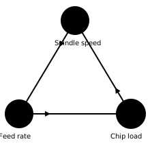
Depth per pass is the axial layer removed in one cutting pass. A shallow first pass is usually easier to validate than a deep pass because it reduces cutting force and makes unexpected movement easier to stop.
Use the smallest depth that proves the toolpath and workholding. A half-diameter value can be a conservative upper-bound heuristic for some light wood-routing setups, but it is not a maximum for every bit and it is not automatically safe. Reduce it when the tool is long, the material is hard, the machine is flexible, the pocket is narrow, or the workholding is uncertain.
Calculate the pass count by rounding up:
pass count = ceiling(total cut depth / chosen depth per pass)
The final pass must be no deeper than the chosen depth per pass. Leave additional stock when the operation needs a separate finishing pass.
Complete the dry run and workholding check
Before cutting:
- Confirm the active work zero and the total depth.
- Confirm that clamps, screws, the dust shoe, and the collet stay outside the toolpath.
- Run the path with the spindle off at a known safe height.
- Confirm that the tool never leaves the stock unexpectedly and that the final depth is correct.
- Keep the emergency stop accessible and do not defeat a guard, limit, door, or interlock.
Read the cut before changing a parameter
Stop the test if the workpiece moves, the tool deflects, the machine misses steps, the sound changes sharply, or the cut produces smoke or melted material. Inspect:
- Chips: solid chips are generally more informative than fine dust, but the expected form depends on material and tool geometry.
- Sound: harsh squeal, chatter, or a sudden load change is a stop signal, not a reason to keep cutting.
- Edge: burning, fuzz, tear-out, or a dimensional error points to a combination of geometry, engagement, workholding, and parameters.
Change one variable at a time. Record the actual tool, material, work zero, spindle speed, feed, depth per pass, stepover, and result. A recorded failed test is more useful than an unlabelled “good setting.”
The first cut is a verification loop
The goal of the first cut is not the fastest cycle. It is to verify that the machine, work zero, tool, material, workholding, and toolpath agree. Once that setup is documented, improve one variable at a time and keep the original tested record as a rollback point.